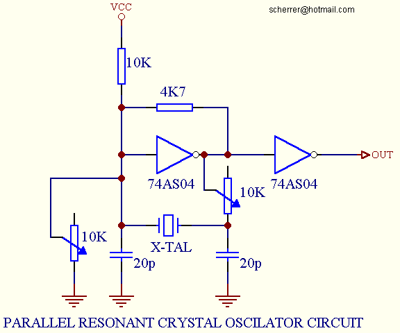

The Figure above shows implementation of a parallel resonant oscillator circuit.
The circuit is designed to use the fundamental frequency of the crystal.
The 74AS04 inverter performs the 180-degree phase shift that a parallel oscillator requires.
The 4K7 resistor provides the negative feedback for stability.
The 10K potentiometer biases the 74AS04 in the linear region. This could be used for external oscillator designs.

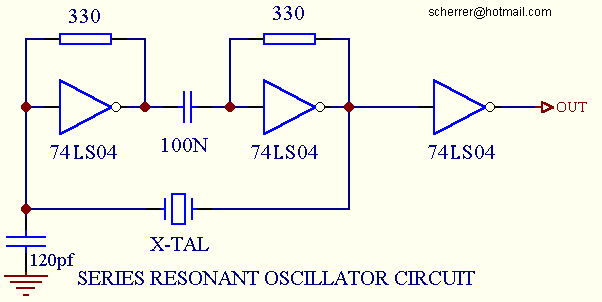
The Figure above shows implementation of a series resonant oscillator circuit.
The circuit is also designed to use the fundamental frequency of the crystal.
The inverter performs a 180-degree phase shift in a series resonant oscillator circuit.
The 330 Ohm resistors provide the negative feedback to bias the inverter in their linear region.

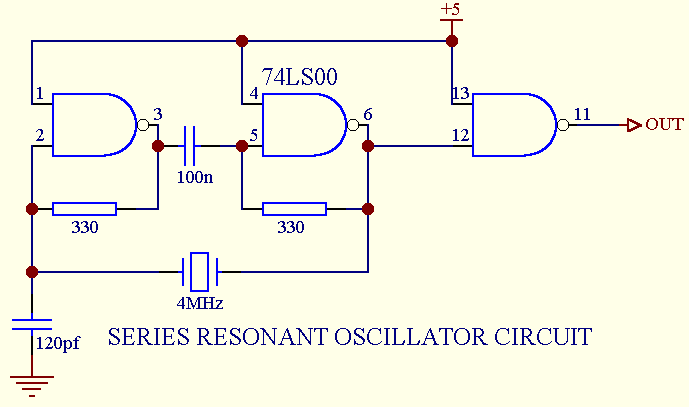
The Figure above shows implementation of a series resonant oscillator circuit, using TTL NAND GATES.
This circuit is tested by me and found working with the following IC types:
7400 Total current consumption is 21 mA.
74LS00 Total current consumption is 15 mA.
74HCT00 Don't use this type, it will NOT work, because the HCT type is too fast.
7400 PIN 6 SCOPE PICTURE
7400 PIN 11 SCOPE PICTURE
74LS00 PIN 6 SCOPE PICTURE
74LS00 PIN 11 SCOPE PICTURE

Links: